ICH Q1B Photostability tests seen in a whole new light
The 1996 guideline CPMP/ICH/279/95 Q1B describes the process for carrying out photostability tests on new active substances and medicinal products.
It stipulates the following:
- Cool white fluorescent lamps with an output similar to that stipulated in ISO 10977 (1993).
- UVA fluorescent lamps with a spectral distribution of 320 nm to 400 nm and a maximum energy emission of between 350 nm and 370 nm. A significant proportion of the waves must be within the ranges of 320 nm to 360 nm and 360 nm to 400 nm.
- The samples should be exposed to visible light (VIS) for at least 1.2 million lux hours and to UVA for at least 200 watt hours per square meter.
The specifications listed above are well known. Less familiar, however, are the intricacies that need to be taken into account when implementing the ICH Q1B guideline in photostability chambers featuring ICH-compliant irradiation facilities.
This blog article introduces two light photometry methods for photostability tests that comply with ICH Q1B, discusses ICH-compliant light sources, and considers the key pros and cons.
Which light sensors are better: planar or spherical? For us, there’s no competition
Two types of light sensors are available for ICH Q1B photostability tests – detectors with a flat sensor surface (planar sensors) and detectors with a spherical sensor surface (spherical sensors). There are two major differences between them – in one case, the sensor calculates the intensity of the radiation, whereas the other measures the actual radiation intensity.
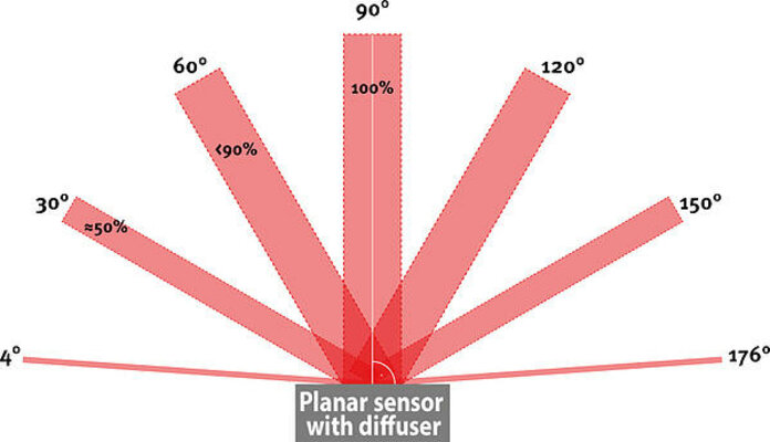
Lambert’s cosine law states that radiation intensity decreases as angles become more oblique. In order to compensate for this reduction, planar sensors with diffusers use what is known as cosine correction. This means that only a small proportion of the radiation that hits the sensor surface is actually measured – the radiation that hits at a 90° angle. For all other angles of incidence (see Figure 1), the radiation intensity is calculated using a mathematical equation.
This is why BINDER does not recommend using planar sensors with diffusers to test the photostability of new active substances and medicinal products. The same applies to planar sensors without diffusers, as they record even less of the actual radiation intensity.

Figure 1: Lambert’s cosine law states that radiation intensity decreases as angles become more oblique. As a result, the planar sensor needs cosine correction. The image shows the angle of incidence on the planar sensor surface with the percentage of incoming radiation in each case, compared to an angle of incidence of 90° (100%).
The second difference relates to the hemispheres of measurement. As Figure 1 shows, a planar sensor can only observe radiation above the sensor surface. It cannot record radiation that has an angle of incidence of either 0° or 180°. In addition, it cannot record any radiation from below.
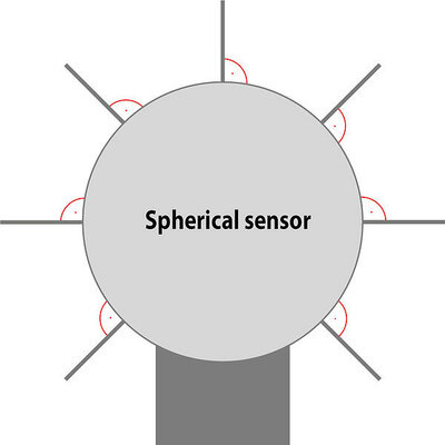
In complete contrast to this, the spherical sensor measures the actual radiation intensity from all directions, meaning that it even records scattered radiation (Figure 2). The radiation always hits the sensor at a 90° angle, which removes the need for cosine correction. The actual radiation intensity is measured rather than calculated.

Figure 2: A spherical sensor makes it possible to measure the radiation intensity from all directions.
As the spherical sensor is the only sensor type that actually measures radiation intensity and records scattered radiation, we have been using exclusively spherical, freely positionable sensors in our KBF LQC photostability chambers for years now.
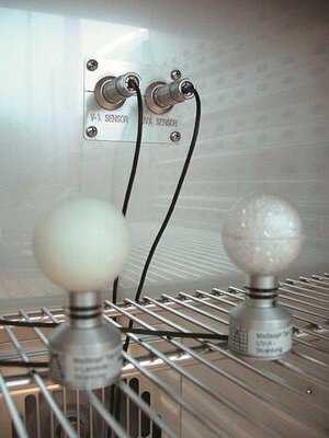
LQC stands for Light Quantum Control™ and is our patented light photometry method for photostability tests. Two spherical sensors that can be freely positioned (Figure 3) control the light dosage of UVA (at least 200 watt hours per square meter) and visible light (at least 1.2 million lux hours). Once the light dosage is achieved, the chamber switches off automatically.

Figure 3: Two golf ball-sized spherical sensors can be freely positioned in the KBF LQC chamber to measure UVA and visible light (VIS).
BINDER does not advise using permanently installed sensors, as it can be difficult to fit samples and batches around them.